Reverse Z-Buffer
The Z-Buffer, or Depth-Buffer, is used in computer graphics to determine the visibility of objects in each pixel.
Every time we draw an object, we also store the distance to the camera in the Z-Buffer.
The next time we draw an object, we can check in the Z-buffer which was the previous value stored in the Z-Buffer. If the value in the Z-Buffer is closer than the object we are drawing, we know the object is occluded, so we don’t draw the pixel. This technique is sometimes called depth testing.
The depth testing approach is ubiquitous in all graphics engines, and so is the case for Evergine. However, as we will see, the naive approach doesn’t give the best results, in terms of accuracy. In this release we have introduced Reverse Z-Buffering, which greatly improves the precision, especially for distant objects.
Traditional Z-Buffer
The traditional approach for Z-buffering stores depth values normalized in the [0, 1] range. Where 0 is the closest value, and 1 is the furthest.
In the following picture we have a 3D camera that looks at some cube.
The green line represents the “near” plane; pixels closer than the near plane are clipped (discarded).
The red line represents the “far” plane; pixels further than the far plane are clipped.
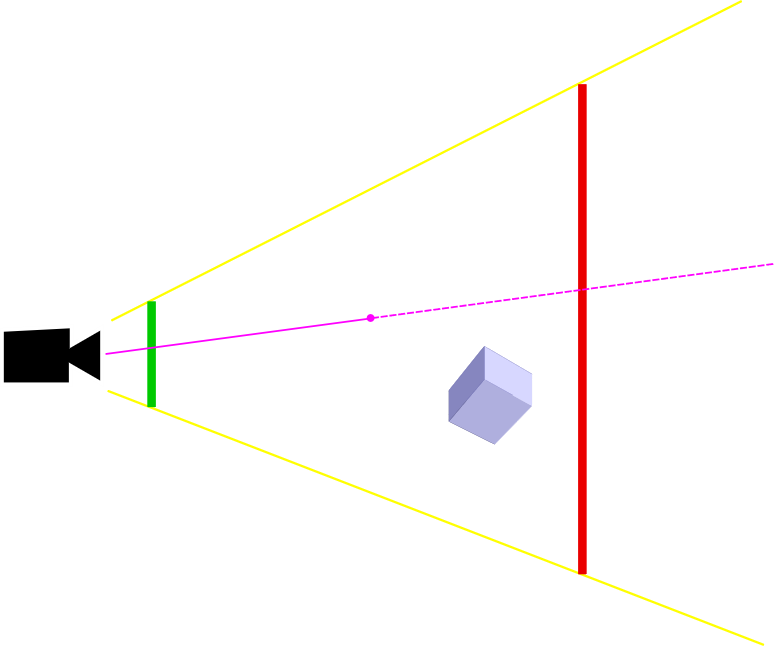
The magenta line represents the distance to the pixel we are drawing (d).
The normalized depth buffer value will be computed using the formula:
depthBuffer=(far)/(far-near)-(far⋅near)/(far-near)⋅1/d
Notice that if d is equal to near, the resulting value is zero.
Similarly, if d is equal to far, the resulting value is one.
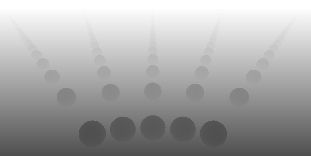
In the following picture, you can see how a typical depth buffer could look like.
Precision issues
In order to show the accuracy problems that can happen with traditional Depth-Buffering, we have constructed the following demo.
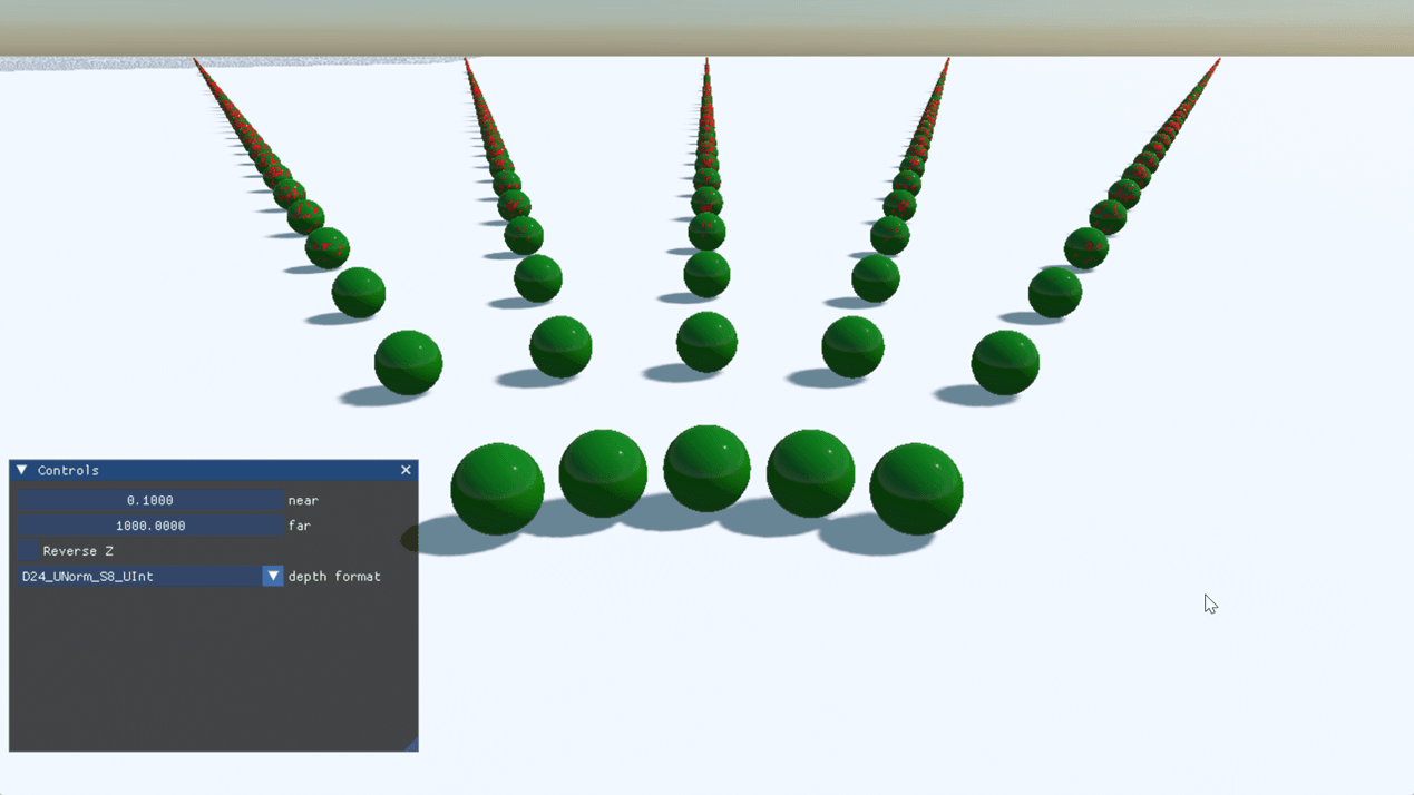
The spheres in this scene are actually two spheres: one inside another.
The disposition of these layered spheres is depicted in the following picture. The two layers are placed very close together.
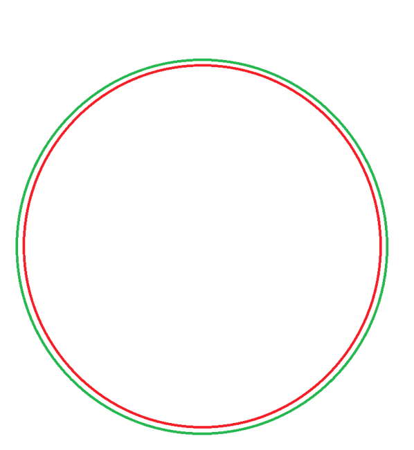
Obviously, the inner red sphere should not be visible. However, as you can see in our demo, as the distance to the camera increases, we start to see the red artifacts.
The phenomenon is known as aliasing. Due to numerical representation precision, once the depth values have been normalized, they map to the same numerical value, so we can’t tell which one is closer.
One option is to increase the number of bits used to represent the value in the Depth-Buffer, but most hardware can’t go beyond 32 bits, and 32 bits are not enough.
Reverse Depth
This accuracy problem can be addressed using a technique called Reverse Depth-Buffering.
The idea behind this technique is very simple. Instead of the regular formula used for computing the normalized depth:
depthBuffer=(far)/(far-near)-(far⋅near)/(far-near)⋅1/d
We swap the near and far planes:
depthBuffer=(near)/(near-far)-(near⋅far)/(near-far)⋅1/d
With this formula, the near plane maps to 1, and the far plane maps to 0. So the depth buffer looks inverted.
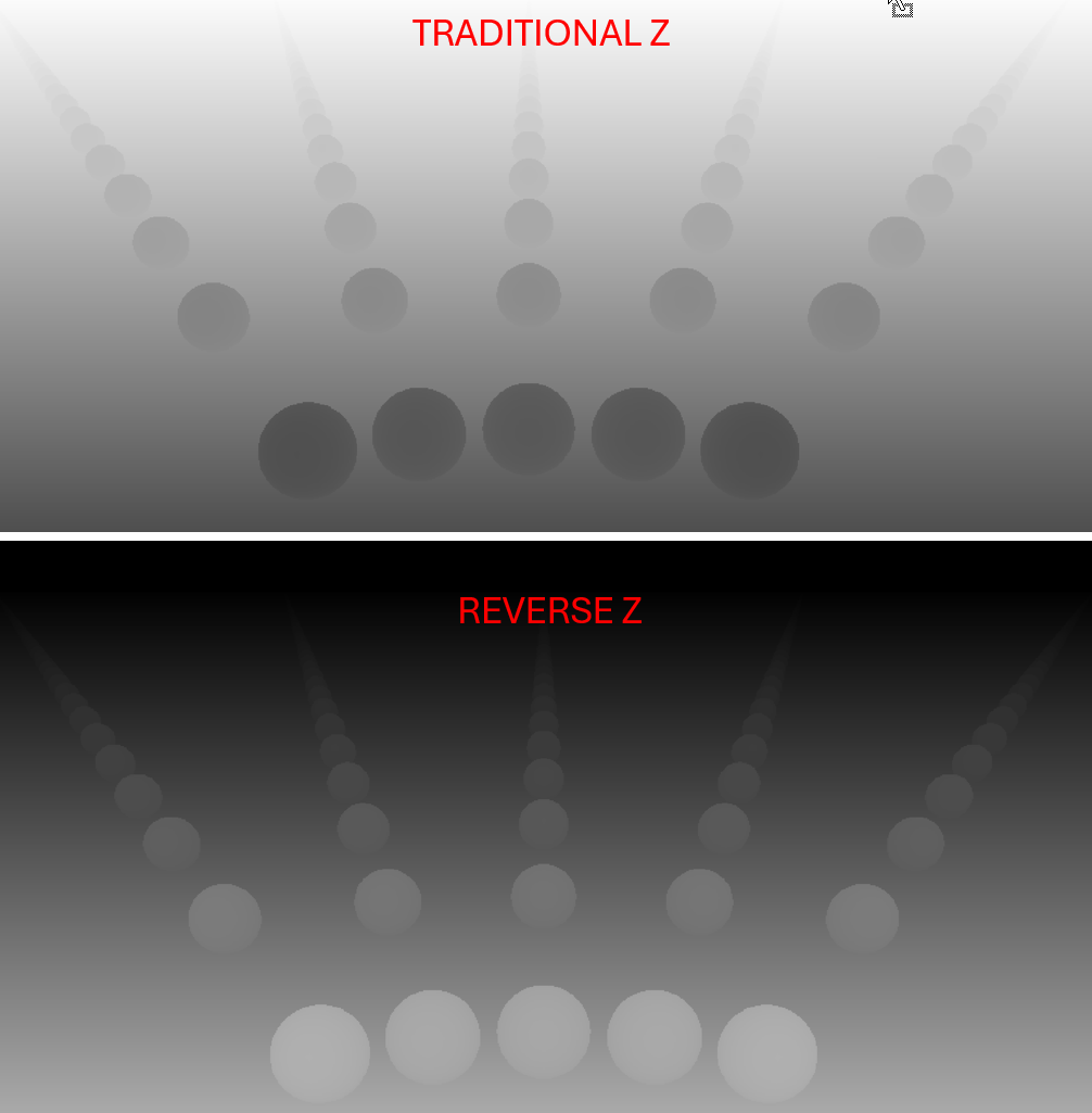
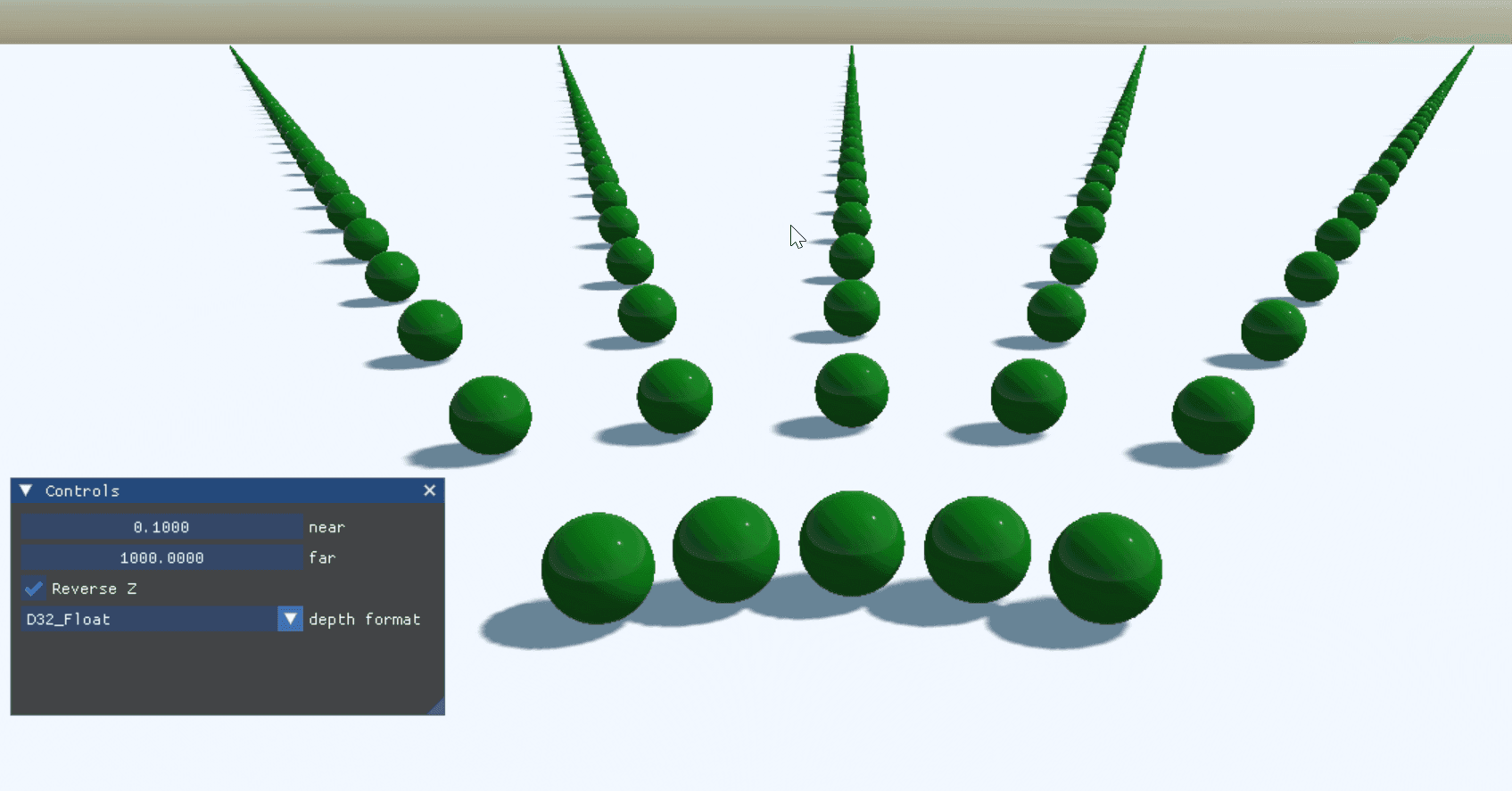
With this small change, together with float depth format, our demo goes all green.
Why does Reverse-Z improve accuracy?
Reverse-Z is such a simple technique: just swap the near and far planes. Yet, results are so good.
Also, the technique seems to be extremely robust; selecting the near and far planes doesn’t require fine adjusting anymore.
Actually, you can set just the far plane to infinity and everything will work perfectly fine. Being able to handle an infinite viewing distance is a big deal for applications that need to handle huge worlds. For example, rendering the entire Earth, as we do in our new Cesium Addon. The near plane can also be much closer, although it can’t be zero.
If you are wondering why Reverse-Z works, in this section we will go deep into the mathematics and technical details.
UNorm and Float representations
Projected depth values are stored in the [0, 1] range.
There are infinitely many real numbers between 0 and 1. However, computers can’t represent all of them exactly, in the same way you can’t write all the digits of pi on paper. So computers will use different representations to approximate real numbers, just like you can approximate pi by writing the first 7 digits, for example.
There are two types of formats used to represent the depth values in the depth buffer: UNorm and float.
UNorm stands for unsigned normalized. An unsigned integer is used to represent real numbers in the [0, 1] range.
Represented values are uniformly distributed in the [0, 1] range.
The following image depicts UNorm represented values. As you can see, spacing between represented values is constant.

Float stands for floating point representation.
Float representation covers the range (-∞, +∞).
Single precision floats use 32 bits, which are split into 3 parts: sign, exponent, and fraction.

(Source: https://en.wikipedia.org/wiki/Single-precision_floating-point_format#/media/File:Float_example.svg)
We can’t cover all the details of floating point notation in this article, so I will just leave these two links for the curious reader: https://floating-point-gui.de, https://en.wikipedia.org/wiki/Single-precision_floating-point_format.
What’s important to know about floats, for the context of our problem, is the way in which represented values are distributed in the range [0, 1], which is the range projected depth values are mapped to.

As you can see in the previous figure, samples are not distributed uniformly. There is more precision devoted to values closer to zero. This is an interesting property for scientific computing applications, but we will also take advantage of this peculiarity.
Now let’s come back to our depth projection formula:
depthBuffer=(far)/(far-near)-(far⋅near)/(far-near)⋅1/d
If we plot this formula, we will get this curve:
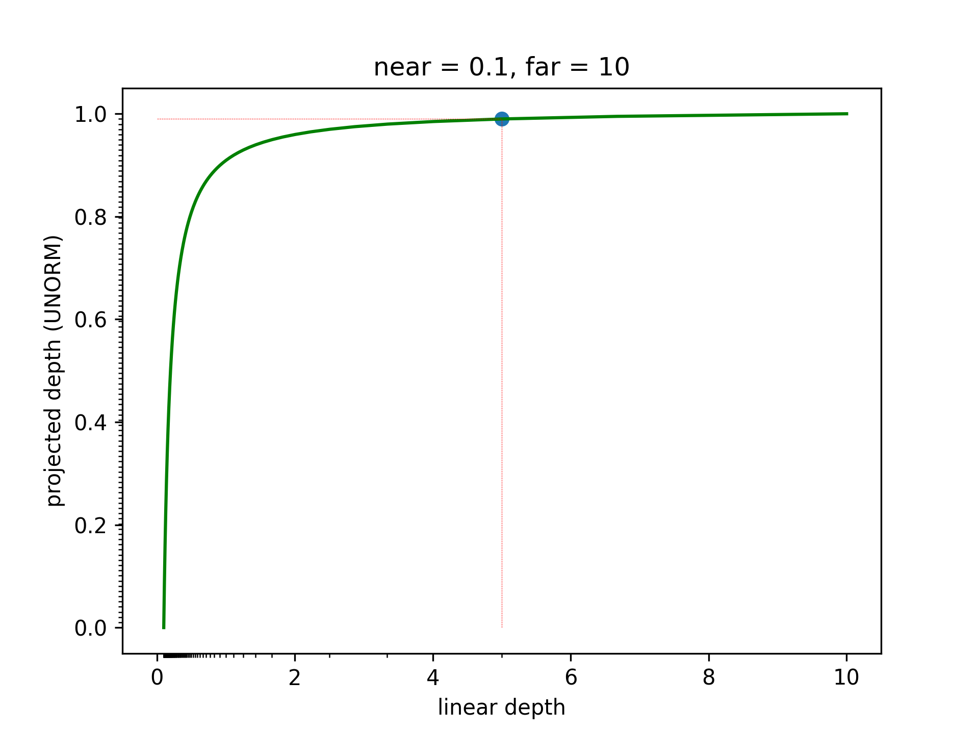
The X axis is the linear depth. The Y axis gives the projected depth to [0, 1] range.
Notice how quickly this function grows.
In the Y axis you can see the samples are uniformly distributed, as we are using UNorm representation.
The X axis has a series of small ticks. Those correspond to the uniformly distributed ticks in Y, before projecting. Notice how most ticks are gathered close to the near plane, while the density of ticks is very low as you get to the far plane.
And that was with a very favorable choice of the near and far plane. Look what happens with near = 0.1, and far = 100.
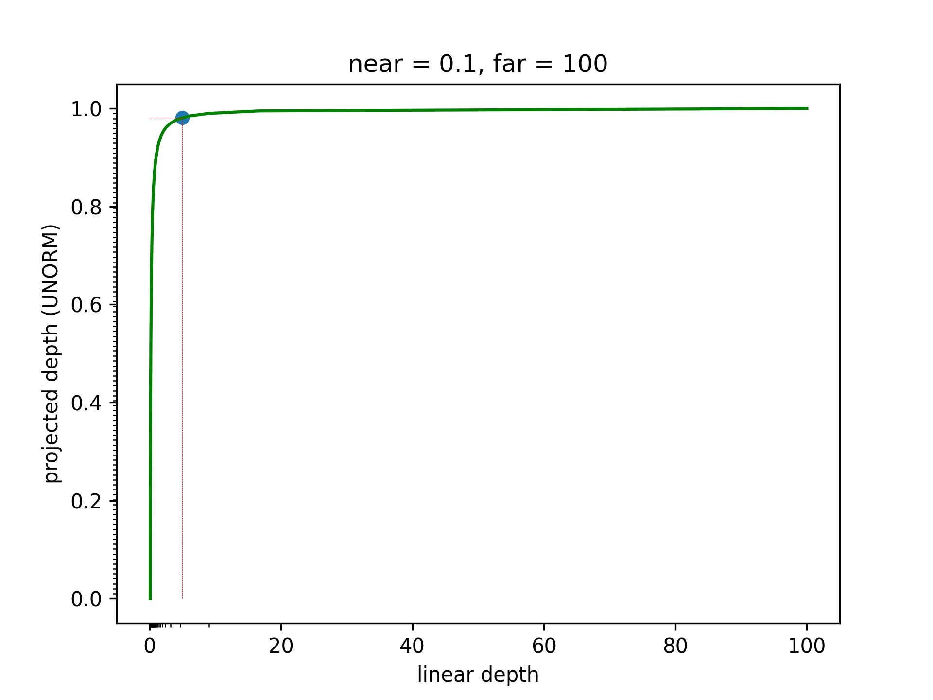
The problem here is that the depth values from 20 to 100 all map to 1. So after we have projected them, we are not able to tell if 45 is lower than 46.
Using floating point notation doesn’t help here. In fact it makes it even worse, as represented linear depth values will be even more concentrated towards near.
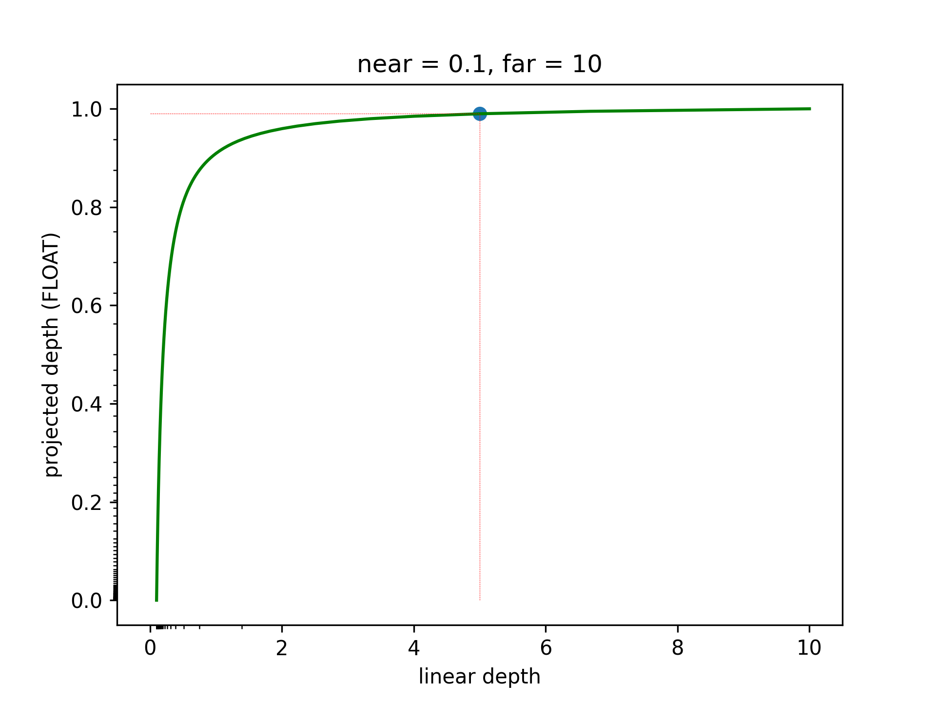
So far we have seen there are two things that contribute to the uneven distribution of samples, favoring values closer to the near plane: 1) The curve of the projection formula 2) Floating point notation
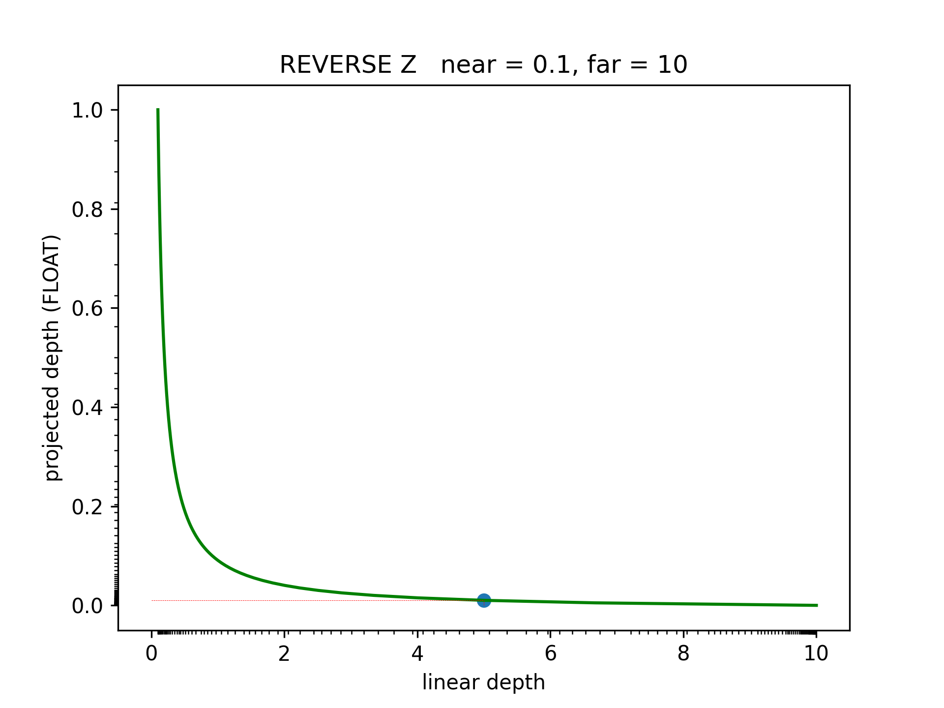
The idea of Reverse-Z is to flip the projection formula. That will create the opposite distribution of samples, favoring distances close to the far plane. Floating point notation having the opposite effect, will compensate for it, and we end up with a more balanced distribution of samples. Look at the distribution of ticks in the X axis of the following picture.
How Reverse Z affects you as Evergine user
After you update to the new version, reverse depth will be enabled automatically.
For most projects, this will not have any implications, but below are two use cases that might break.
Shaders that use the depth buffer
If you have written custom shaders that read the raw depth buffer, you will need to change your shader accordingly.
We have added some shader parameters that will help you convert reverse-depth to forward-depth.
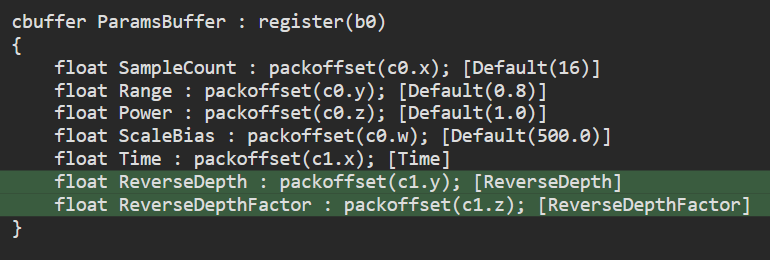
ReverseDepth is 0 if we are rendering with traditional forward depth buffering, and 1 if we are using reverse depth. However, it will always be 1, from now on.
The ReverseDepthFactor is meant to be used for converting to forward depth with the following function:
// This is a function that converts a reverse-depth value to forward-depth, if needed, without branching
inline float forwardDepth(float depth)
{
    return depth * ReverseDepthFactor + ReverseDepth;
}
Custom render layers
If you have custom Render Layers in your project, you will have to invert the depth test condition.
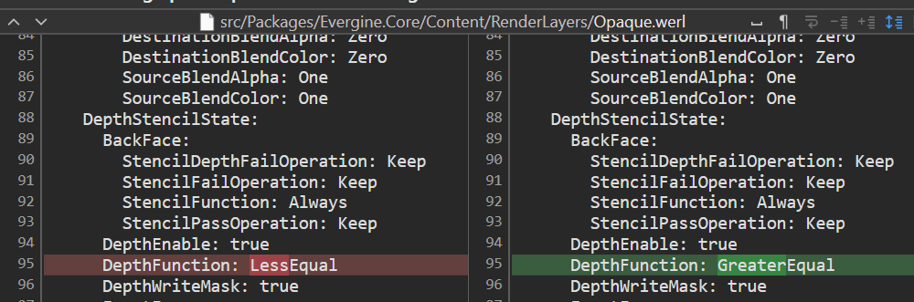
In the Evergine documentation for the new release, you will find a migration guide with some scripts designed to automate this process.